Interface Control Document
Warning
This ICD was written for NOS-T v1.0 (February 2022) using the MQTT protocol with Solace PubSub+ as the message broker. The current version of NOS-T uses the AMQP protocol with RabbitMQ and includes additional command types (Freeze and Resume) not covered in this document. See the API Reference for current documentation.
Release |
Date |
Description |
|---|---|---|
v.1.0 |
Feb. 1, 2022 |
Initial release of the ICD and documentation of NOS-T Tools library. |
TABLE OF CONTENTS
1.3 Conventions used in this Document
1.4 Definitions and Glossary of Terms
1.5 Obtaining Documentation, Tools, and Information
3.2.3 Example MQTT Messaging Client
4.4 Test Case-Specific Execution Requirements
5.3 Tools, Templates, and Techniques
5.4 Ensuring NOS-T Compatibility
Preface
NOS-T Introduction
The New Observing Strategies (NOS) initiative within the NASA Earth Science Technology Office (ESTO) Advanced Information Systems Technology (AIST) program envisions future Earth science missions with distributed sensors (nodes) interconnected by a communications fabric that enables dynamic and intelligent operations. Some NOS concepts resemble systems-of-systems or collaborative systems where operational authority is distributed among multiple systems, necessitating new methods for systems engineering and design to cope with more decentralized control over constituent systems.
The New Observing Strategies Testbed (NOS-T) is a computational environment to develop, test, mature, and socialize new operating concepts and technology for NOS. NOS-T provides infrastructure to integrate and orchestrate user-contributed applications for system-of-systems test cases with true distributed control over constituent elements. The overall concept, illustrated in Figure 1, interconnects individual user applications and a NOS-T manager application via common information system infrastructure to coordinate the execution of virtual Earth science missions. NOS-T enables principal investigators to conduct test runs in the same environment, systematically changing variables to assess the overall efficacy of the proposed new observing strategies. Recorded data and outcomes provide evidence to advance technology readiness level and improve upon or innovate existing Earth science measurement techniques.

Figure 1. New Observing Strategies Testbed Comprised of User Systems and the NOS-T System.
NASA/ESTO contracted with the Systems Engineering Research Center (SERC), a University-Affiliated Research Center (UARC) of the United States Department of Defense, to design and develop a framework for the NOS-T. The SERC comprises 22 member universities across the country with deep expertise in systems engineering and is headquartered at Stevens Institute of Technology in Hoboken, New Jersey. The SERC develops partnerships between academia, government, and industry with a focus on solving systems challenges critical to national security through systems research. As an independent actor, the SERC can identify and develop systems engineering solutions free from real or perceived conflicts of interest with existing NASA centers.
Based on input from NASA/ESTO, the NOS-T design and development follows six top-level guiding principles:
Geographic distribution: user systems connect using a standard network interface (rather than integrating software at a centralized site) to allow remote participation from multiple sites.
Multi-party participation: user systems interact with other systems by sending and receiving information using standard network protocols (rather than software source code or compiled executables) to run test cases across organizational or institutional boundaries.
Security: transport layer encryption and access control rules restrict information exchange and hosted NOS-T system components conform to required information system security policies.
Modularity: loose coupling provided by a well-defined application interface allows individual user applications to be replaced, tested, and validated without modifying the rest of the testbed.
Extensibility: test cases can be updated by adding, removing, or changing capabilities of individual user applications which are integrated using the generic NOS-T system capabilities.
Usability: members of the Earth science community can develop new test campaigns and user systems by leveraging existing software and knowledge without a substantial learning curve.
As a result of these guiding principles, NOS-T adopts a simpler software architecture than existing distributed simulation standards like Distributed Interactive Simulation (DIS, IEEE Std. 1278) and High-Level Architecture (HLA, IEEE Std. 1516). Most frequently used in defense applications, DIS and HLA provide comprehensive distributed simulation capabilities but also require substantial resources to learn, develop, and execute compliant applications. Unlike these architectures, NOS-T uses a simple event-driven protocol layered over Message Queuing Telemetry Transport (MQTT), itself a lightweight publish-subscribe messaging protocol with high-quality open-source implementations available in most languages, to support real-time and scaled real-time execution modes using standard computer networks. There are several advantages but also some disadvantages to pursuing this system architecture discussed in this document.
This Interface Control Document and User’s Guide provides information about the NOS-T system architecture, components, and key interfaces required for users to take full advantage of its capabilities. While further NOS-T tools and capabilities are still under development, this brief describes the fully functional features as of version 1.0 in February 2022.
Purpose of this Document
The purpose of this document is to provide potential NOS-T users with a complete description of the relevant functions and interfaces of the system along with practical how-to information for preparing for and executing test campaigns using the system.
Conventions used in this Document
This document occasionally uses code or pseudo-code blocks offset in gray boxes, e.g.:
print("Hello World!")
Specific code examples are descriptive (not normative) examples of the NOS-T ICD.
Definitions and Glossary of Terms
Table 1 provides a list and definition of terms and acronyms as used by the NOS-T system to standardize the taxonomy of users and operators can interact.
Term |
Definition |
|---|---|
AIST |
Advanced Information Systems Technology |
Campaign (or Test Campaign) |
For purposes of NOS-T a Campaign or Test Campaign will be associated with a top-level science objective. Test Campaigns comprise Test Cases for this objective. |
DOE |
Design of Experiments |
ESTO |
Earth Science Technology Office |
Instrument Concept |
For the purposes of the NOS-T Framework, an instrument concept is contained within the definition of the space element(s) that comprise the Space Mission Architecture. |
ITAR |
International Traffic in Arms Regulations |
Message |
Unit of information exchange using the NOS-T service bus. |
Mission |
For the purposes of the NOS-T Framework, a mission is defined to include all the elements of a Space Mission Architecture (see below). |
Mission Concept |
For the purposes of the NOS-T Framework, a mission concept will be synonymous with a Mission (see above). |
NOS |
New Observing Strategies |
NOS-T |
New Observation Strategies Testbed |
Protocol |
Technical mechanism by which messages are exchanged on the NOS-T service bus. |
Scenario |
For purposes of NOS-T a Scenario will be considered synonymous with Test Case (see below). |
Science Concept |
For the purposes of the NOS-T Framework, the science concept defines the overall scientific objectives of the mission (e.g., detect wildfires, measure snow depth). |
SERC |
Systems Engineering Research Center |
Space Mission Architecture |
According to Space Mission Analysis and Design - Core (Larson et al.) A Space Mission Architecture includes subject, orbit, spacecraft, launch vehicle, ground systems, mission operations systems, and communication architecture. |
SRL |
System Readiness Level |
STM |
Science Traceability Matrix |
Study or NOS-T Study |
For the purposes of the NOS-T Framework, a Study (or NOS-T Study) is synonymous with a Test Campaign. |
Test Case |
For the purposes of NOS-T, a collection of Test Cases comprises a Test Suite. Following a Design of Experiments (DOE) approach, each Test Case defines specific Space Mission Architecture initial conditions (spatial, temporal, natural), individual node behaviors or individual node performance metrics along with any boundary conditions to be managed by the NOS-T for which data will be collected during the Test Case Execution. |
Test Case Execution |
For the purposes of NOS-T, a Test Case Execution completes a Test Case in the NOS-T environment from beginning to end as defined by the Test Case parameters and the boundaries of the Test Suite. |
Test Suite |
For the purposes of NOS-T, a Test Suite is composed of individual Test Cases. The Test Suite is comprised of models that define elements of the Space Mission Architecture including individual nodes within that architecture along with their behavior and performance. |
TRL |
Technology Readiness Level |
Obtaining Documentation, Tools, and Information
To obtain copies of development and verification tools cited in this document, please contact the principal investigator:
Disclaimers
The Systems Engineering Research Center (SERC) is a federally funded University Affiliated Research Center managed by Stevens Institute of Technology.
This material is based upon work supported, in whole or in part, by the U.S. Department of Defense through the Combat Capabilities Development Command (CCDC) Armaments Center (AC) and NASA Goddard Space Flight Center (GSFC) under Contract W15QKN-18-D-0040 (Task Order W15QKN20F0551).
Any views, opinions, findings and conclusions or recommendations expressed in this material are those of the author(s) and do not necessarily reflect the views of the United States Department of Defense nor CCDC-AC or NASA.
This Stevens Institute of Technology and Systems Engineering Research Center Material is furnished on an “as-is” basis. Stevens Institute of Technology makes no warranties of any kind, either expressed or implied, as to any matter including, but not limited to, warranty of fitness for purpose or merchantability, exclusivity, or results obtained from use of the material. Stevens Institute of Technology does not make any warranty of any kind with respect to freedom from patent, trademark, or copyright infringement.
The NOS-T development team has made every effort to ensure the accuracy of the information contained in this document. However, in the dynamic environment of software development it is possible that some changes do not get precisely captured. Please refer to the latest version of this document and all system software and tools.
Overview Guide
Investigator Journey
The purpose of NOS-T is to enable new technology principal investigators (PIs) and technology program management (PM) to evaluate the efficacy of newly proposed observation strategies for Earth science missions. Figure 2 illustrates the notional investigator’s journey from concept, to proposal, to test campaign to analysis and publication.

Figure 2. Investigator Journey Map from Concept through Publication illustrating interaction with NOS-T. (click to enlarge)
The three swim lanes correspond to the NOS-T Operator (orange), technology PI (teal), and technology PM (green) actors. During the formulation phase, the NOS-T Operator defines the interface control document (ICD) for the NOS-T platform. The PI develops a new proposal for a test campaign to evaluate a new technology responsive to PM application areas. The PM reviews and selects proposals to provide authority to proceed (ATP).
Next, during the validation phase, the PI defines and develops the user applications that will participate in the NOS-T test campaign, which may be reviewed by the PM. During the initialization phase, the NOS-T operator receives the user applications and performs a verification test for ICD compliance.
During the execution phase, the NOS-T Operator conducts a set of test case executions, comprising the test campaign, to provide preliminary data products to the PI to review and make any necessary adjustments to the user application. When ready, the NOS-T Operator executes a final set of test cases in the test campaign to produce data products to be delivered to the PI for analysis. Finally, the PI analyzes and reports results to the PM prior to publishing findings and providing lessons learned to the NOS-T Operator to continuously improve operations.
Test Campaign Checklist
The following checklist provides an overview of principle investigator Test Campaign activities from start to finish. The nature of each Test Campaign, the number and type of applications and their interactions are essentially limitless. However, because of the flexible NOS-T interface architecture, the basic approach to leveraging the capabilities of NOS-T to execute the campaign are virtually identical.
Pre-Campaign Preparation (see Section 5.1)
Define investigation hypothesis(es)
Develop test campaign architecture
Test campaign(s) to answer broadly-scoped research questions
Test suites to answer narrowly-scoped research questions
Test cases to evaluate specific configurations
Create test campaign plan
Develop test campaign application(s)
Define test campaign application-to-application interfaces (what data and how)
Verify and validate test campaign applications in stand-alone operations
Perform pre-campaign NOS-T-to-test campaign application “fit check”
Test Campaign
Set up test campaign environment
Perform check-out run
Execute test campaign plan
Collect test campaign data (test cases and test suite(s))
Post-Test Campaign
Analyze data
Publish results with respect to original hypotheses
Review test campaign for lessons learned
Improve NOS-T process and revise test campaigns as necessary
NOS-T Description
This section provides a detailed description of the NOS-T architecture and how state changes are communicated via messages published and subscribed to topics.
System Architecture
The NOS-T system architecture follows a loosely coupled event-driven architecture (EDA) where member applications communicate state changes through events that are embodied as notification messages sent over a network. EDA provides enhanced scalability and reliability over other software architectures by replicating event handling functions across infrastructure instances while maintaining modularity between applications through a simple event-handling interface. NOS-T can also be described as a service-oriented architecture (SOA) as applications trigger services in response to events.
The NOS-T architecture relies on a centralized infrastructure component called an event broker (synonymous with message broker) to exchange event notifications between applications. A broker simplifies the communication structure because each member application (client) only directly connects to the broker, rather than requiring each application to directly connect to every other application.
While there are many alternative broker implementation options available, NOS-T adopts the Solace PubSub+ Standard Edition event broker[1], a proprietary but freely available commercial product supporting up to 1000 concurrent connections and 10,000 messages per second. PubSub+ supports and interoperates among several protocols and several open protocols including Message Queuing Telemetry Transport (MQTT), Advanced Message Queuing Protocol (AMQP), and Representational State Transfer (REST)[2]. All protocols share similar messaging constructs but exhibit some minor differences in implementation and library availability. To simplify its initial release, NOS-T only uses MQTT.
NOS-T hosts an instance of PubSub+ on a server in the Science Managed Cloud Environment (SMCE), a managed cloud infrastructure for ESTO projects[3]. SMCE both provides the flexibility of cloud services to customize configuration settings outside of a firewalled network and the security of required controls for a FISMA Low operating environment. The PubSub+ platform uses a publish-subscribe messaging pattern which designates applications (clients) as publishers (producers of events) and subscribers (consumers of events). Each application can publish or subscribe to multiple types of events.
The two top-level NOS-T system components include the NOS-T System which is fixed for all test cases and the User System which is tailored to each unique test case. The NOS-T System, administered by an NOS-T operator, includes the event broker infrastructure and a manager application that orchestrates test runs. The test operator issues commands via a manager application, either via console or web-based graphical user interface (GUI). Figure 3 illustrates how the manager publishes events to other applications through the event broker. The manager application publishes messages following the topic and payload specifications in Section 3.2.1.
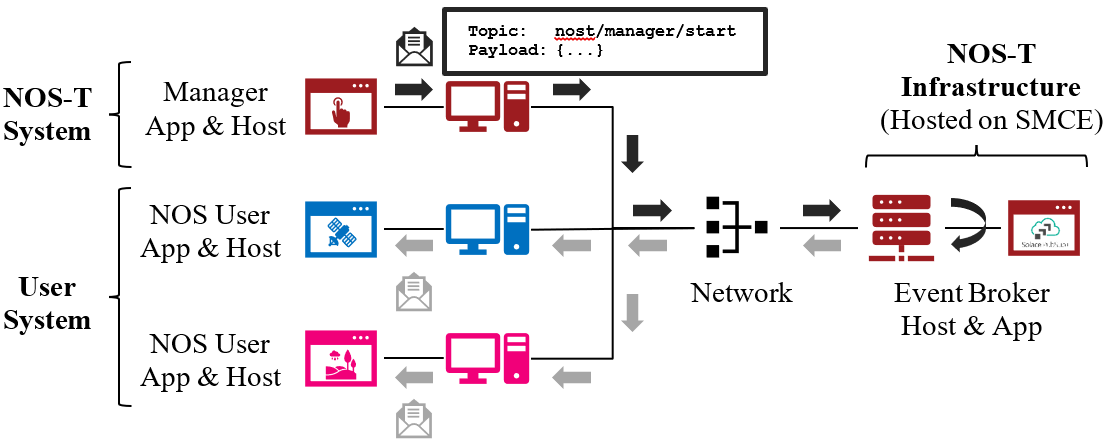
Figure 3. NOS-T System Architecture Illustrating the Route of a Message from Publisher to Subscribers.
The User System consists of user applications developed and operated by each test case participant. User applications run on separate hosts controlled by each participant and can be variably scoped to model an entire observing system or individual components such as sensors, communication links, tasking or scheduling algorithms, forecasting models, or environmental data (e.g., nature run data sets for observing system simulation experiments). Each user application must meet the basic NOS-T interface requirements for orchestration (namely, subscribing to and responding to manager commands) plus any additional test case-specific interface requirements agreed upon by the participants. There are no general restrictions on software language, host platform, physical location, or other implementation details for user applications.
System Interface
The broker interconnects applications to allow distributed users to participate in test case executions. The interface between the User System and NOS-T System consists of a message protocol to send and receive information units and a message format to structure their contents.
Message Protocol
All NOS-T events are communicated by sending or receiving messages using the standard MQTT messaging protocol. Connecting to the MQTT server is the most important high-level requirement, although other messaging protocols may be incorporated in the future based on the interoperability of the Solace PubSub+ event broker. The general steps for making this connection are shown in Figure 4, where MQTT Server refers to the event broker. First, a user instantiates an MQTT client using a language-specific implementation library. Next, the user sets client credentials (username and password) required for authentication and authorization and configures Transport Layer Security (TLS) certificates to encrypt messages. Finally, the user connects the client to the server to establish communication.
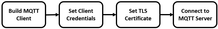
Figure 4. MQTT Connection Process
Each application identifies event topics to which it publishes and subscribes messages. A topic is a hierarchical addressing scheme written as forward slash (/) delimited labels (e.g., nost/manager/start). The first topic level (e.g., nost) designates a NOS-T namespace (prefix) unique to each a test case execution, allowing multiple test cases to run simultaneously on the same broker without conflicts. The second topic level (e.g., manager) designates an application namespace controlled by a member application. Additional topic levels (e.g., start) refine the application namespace to differentiate event types, with up to 128 total topic levels.
Message topics need not be defined in advance; however, the NOS-T operator can configure access control rules in the PubSub+ application to grant client-specific subscribe/publish (i.e., read/write) permission for specific topics. Subscriptions can also use wildcard characters to receive messages on multiple topics. For example, the # character in MQTT represents a multi-level wildcard (e.g., nost/manager/#) and the + character represents a single-level wildcard (e.g., nost/+/status).
Overall message routing between publishers and subscribers can be graphically depicted in several ways. Figure 5(A) depicts a physical network diagram with topic-specific conduits between applications and the broker. Application A publishes an event message (of type X) to topic nost/A/X which is routed to two subscribers: B subscribes to the same topic (nost/A/X) and application C subscribes to a wildcard topic (nost/A/#). Figure 5(B) presents a more compact diagram showing at application A publishes event type X which is consumed by (subscribed to by) applications B and C. More complex system concepts introduce event feedback loops between applications to indicate dynamic and responsive operations.

Figure 5. Publish-Subscribe Messaging Pattern in (A) Physical Network and (B) Event-oriented Diagrams. (click to enlarge)
Message Format
Messages are defined by a topic and payload. Each message must be published to exactly one topic (no wildcards). The message payload (body) contains event data structured as either a string (text) or byte array (raw). PubSub+ can be configured for message payload sizes up to 30 MB.
The NOS-T manager sends messages with payload strings encoded in JavaScript Object Notation (JSON) which defines data structures that are easily readable both by computers and humans. JSON encodes string, numeric, and Boolean data types and list and dictionary data structures in a text-based notation. Additional encoding allows representation of more complex data types, like timestamps, using standards like ISO-8601. For example, the manager-issued start event has the following JSON structure:
{
  "taskingParameters": {
    "startTime": "2021-04-15T12:00:00+00:00",
    "simStartTime": "2019-03-15T00:00:00+00:00",
    "simStopTime": "2019-03-19T00:00:00+00:00",
    "timeScalingFactor": 60
    }
}
Using JSON to encode payload strings is optional but recommended for user-defined event messages because it allows for simple parsing and semantically readable data. While the object schemas (specification of required key names and expected value types) to structure JSON message payloads for new events depend on each application case, the NOS-T manager messages are loosely based on standardized object schemas for the SensorThings Sensing[4] and Tasking[5] APIs. The start event above is based on the SensorThings Task entity with task-specific parameters (startTime, simStartTime, etc.) contained within the taskingParameters dictionary.
Example MQTT Messaging Client
MQTT is the selected messaging protocol for new user applications because of its simplicity and broad support including high-quality open-source libraries for most languages. For example, the Eclipse Paho library (paho-mqtt) is publicly available under an open-source license for the Python language[6].
A simple example below connects a client to the broker (using placeholders for client username and password and the broker host address and port), subscribes to the wildcard topic nost/manager/#, sends a plain text message to the topic nost/example/hello every second (receiving messages while calling the loop() function), and prints out received messages to console using a callback function.
#!/usr/bin/env python3

import paho.mqtt.client as mqtt
import time

# callback to run when a message is received
def on_message(client, userdata, msg):
  print(msg.topic + " " + str(msg.payload))

# instantiate a new client and bind the callback
client = mqtt.Client()
client.on_message = on_message

# connect to the broker and subscribe to a topic
client.username_pw_set(CLIENT_USERNAME, CLIENT_PASSWORD)
client.tls_set()
client.connect(BROKER_ADDR, BROKER_PORT)
client.subscribe("nost/manager/#")

# main execution loop
for i in range(10):
  # publish message to a topic
  client.publish("nost/example/hello", f"Hello {i}")
  # process message events for 1 second
  t = time.time()
  while time.time() - t < 1.0:
    client.loop()
Additional Eclipse Paho features described in the documentation[6] include background threads to process message events (rather than calling the loop() function directly), per-topic callback functions to simplify event handling, and additional configuration options to manage the broker connection.
Manager Events
The NOS-T manager orchestrates user applications by synchronizing key scenario points (e.g., start, changes in time scale, and end) and progressing scenario (simulated) time at a designated pace. During a test case execution, the manager application publishes several types of events to issue commands (control events) and communicate state changes (status events).
All manager events are published to the topic $PREFIX/manager/TYPE ($PREFIX is the test case namespace and TYPE is the control event type) and use JSON for message payload encoding. This section briefly describes the topic and payload for each type of manager event.
Control Events
The manager issues control events to orchestrate a test case execution. The test case execution lifecycle follows the activity diagram in Figure 6 with an initialization, start, optional updates, and a stop event.
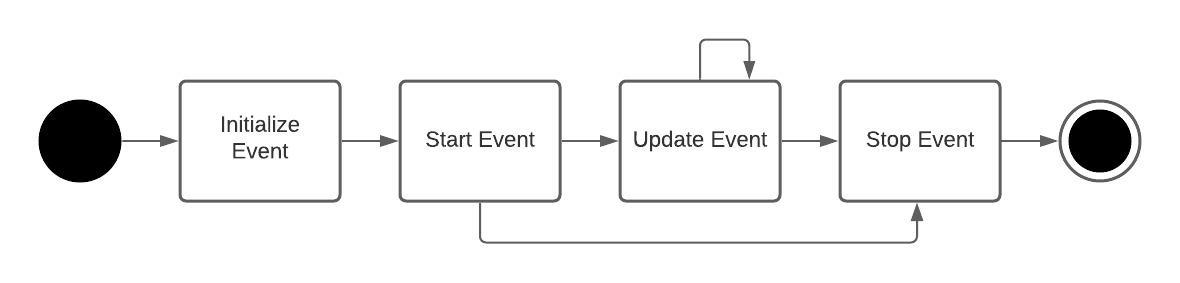
Figure 6. Typical Managed Test Case Execution Lifecycle. (click to enlarge)
The control event message payload builds on the Task entity object schema in the Sensor Things Tasking API[5] with a top-level key taskingParameters to group event-specific parameters. Table 2 lists the four manager control event types described in the following sections.
Event |
Message Topic |
Example Message Payload (JSON) |
|---|---|---|
Initialize |
$PREFIX/manager/init |
{
  "taskingParameters": {
    "simStartTime": "2019-03-15T00:00:00+00:00",
    "simStopTime": "2019-03-21T00:00:00+00:00"
    }
}
|
Start |
$PREFIX/manager/start |
{
  "taskingParameters": {
    "startTime": "2021-04-15T12:00:00+00:00",
    "simStartTime": "2019-03-15T00:00:00+00:00",
    "simStopTime": "2019-03-19T00:00:00+00:00",
    "timeScalingFactor": 60
    }
}
|
Update |
$PREFIX/manager/update |
|
Stop |
$PREFIX/manager/Stop |
{
  "taskingParameters": {
    "simStopTime": "2019-03-21T00:00:00+00:00"
    }
}
|
Initialize Control Event
The NOS-T manager publishes an initialize event to topic $PREFIX/manager/init to specify the temporal context for an upcoming test case execution. It provides bookended timestamps to allow member applications to prepare requisite data and initialize components before a test case execution starts.
Property |
Type |
Description |
|---|---|---|
simStartTime |
ISO-8601 datetime string |
The earliest possible scenario start time. |
simStopTime |
ISO-8601 datetime string |
The latest possible scenario end time (shall be later than simStartTime). |
Start Control Event
The manager publishes a start event to $PREFIX/manager/start to schedule the start of a test case execution. To coordinate scheduled times to a common timing source, the manager synchronizes its system clock via a Network Time Protocol (NTP) request before each test case execution.
Property |
Type |
Description |
|---|---|---|
startTime |
ISO-8601 datetime string |
The earliest wallclock (real-world) time at which to start the test case execution. A test case execution shall start immediately if startTime is undefined or in the past. |
simStartTime |
ISO-8601 datetime string |
The scenario time at which to start the test case execution (shall be within the bounds specified in the initialization event). |
simStopTime |
ISO-8601 datetime string |
The scenario time at which to end the test case execution (shall be within the bounds specified in the initialization event and later than simStartTime). |
timeScalingFactor |
Positive integer |
The constant factor for units of scenario time per wallclock time. |
Update Control Event
The manager publishes an update event to $PREFIX/manager/update to schedule a change in time scaling factor for a test case execution. The manager only considers one pending update at a time such that subsequent update events override the pending one.
Property |
Type |
Description |
|---|---|---|
simUpdateTime |
ISO-8601 datetime string |
The earliest scenario (simulated) time at which to update the time scaling factor. |
timeScalingFactor |
Positive integer |
The scenario time at which to start the test case execution (shall be within the bounds specified in the initialization event). |
Stop Control Event
The manager publishes a stop event to $PREFIX/manager/stop to schedule the end of a test case execution. The most recently published stop event determines the end of the test case execution.
Property |
Type |
Description |
|---|---|---|
simStopTime |
ISO-8601 datetime string |
The earliest scenario time at which to end the test case execution (shall be within the bounds specified in the initialization event). |
Status Events
The manager issues status events to communicate state changes in its local model of the test case execution. The status event message payload builds on the Thing entity object schema in the Sensor Things Sensing API[4] with top-level keys for name, description, and properties to group event-specific parameters. Table 7 lists the two manager status event types described in the following sections.
Event |
Message Topic |
Example Message Payload (JSON) |
|---|---|---|
Time |
$PREFIX/manager/time |
{
  "name": "Manager",
  "description": "Manages a test case execution",
  "properties": {
    "simTime": "2019-03-15T00:00:00+00:00",
    "time": "2021-04-15T12:00:00+00:00"
  }
}
|
Mode |
$PREFIX/manager/mode |
{
  "name": "Manager",
  "description": "Manages a test case execution",
  "properties": {
    "mode": "EXECUTING"
  }
}
|
Time Status Event
During a test case execution, the manager publishes a time status event at topic $PREFIX/manager/time to periodically notify member applications of the current scenario time. Time messages are sent at fixed intervals during a test case execution. Member applications can use time status events to trigger activities for time-evoked execution modes or to synchronize scenario clocks more generally.
Property |
Type |
Description |
|---|---|---|
simTime |
ISO-8601 datetime string |
The current scenario time. |
time |
ISO-8601 datetime string |
The current wallclock time. |
Mode Status Event
The manager publishes a mode status event at topic $PREFIX/manager/mode to notify member applications of changes in its execution mode throughout the execution lifecycle. Mode events provide an alternative to time events for member applications to trigger activities. Manager modes include:
INITIALIZING: started a test case initialization procedure
INITIALIZED: completed a test case initialization procedure
EXECUTING: started a test case execution
TERMINATING: started a test case termination procedure
TERMINATED: completed a test case termination procedure
Property |
Type |
Description |
|---|---|---|
mode |
String |
The current execution mode. |
NOS-T Interface
As described above, the User System consists of user-developed applications as component models of an observing system to be evaluated in a NOS-T test case. User applications must meet generic NOS-T execution requirements as well as test case-specific requirements. This section focuses on how user applications can do that.
To support a diverse set of user applications, NOS-T supports two levels of execution with differing capabilities and complexity of implementation:
Unmanaged: user application(s) run “open-loop” with no interaction with the NOS-T Manager Application.
Managed: user application(s) run “closed-loop,” subscribing to and responding to NOS-T Manager Application control events.
As the unmanaged application cases do not take advantage of the full NOS-T system, they are considered a special case. As a result, they are only briefly described here. The focus of Section 4 will be on managed applications.
Generic NOS-T requirements govern the interactions between the manager and each user application to orchestrate the test case. Test case-specific requirements govern the interactions between user applications to model the integrated concept of operations. Following EDA principles, requirements define an interface protocol (contract) rather than other implementation details. NOS-T execution requirements describe how user applications respond to manager events. Figure 7 illustrates the interface between the manager and a managed user application.

Figure 7. Event Interface between Manager and Managed User Applications. (click to enlarge)
FireSat+ Example
To avoid only describing an abstract interface, we will use a specific example of a managed use case throughout this section. The example is based on the canonical FireSat mission, a fire-detecting spacecraft application case commonly used in space systems literature. Firesat+ is a hypothetical mission to detect and monitor wildfires from low-Earth Orbit via a constellation of satellites rather than a single observer[7]. The FireSat+ Test Campaign scenario demonstrates how user applications can model parts of a fire observation remote sensing system. This simple scenario assumes interactions between four user applications as shown in Figure 8.
Fires/Science application: maintains a table of fire ignition times and locations. Publishes messages containing the location of these fires immediately after scenario time passes the scheduled ignition time. Subscribes to and records first detect and first report timestamps.
Constellation/Satellites application: models spacecraft operations with orbit(s) specified by Two-Line Element(s) (TLEs). Subscribes to fire status events to determine visibility based on propagated orbit location and instrument sensitivity. Publishes a fire detection event when in range of a ground station after observing a fire. Internally logs detection and report times for each satellite in the constellation, but only first detects and reports are published.
Ground application: models a communications ground station. At beginning of the simulation publishes ground station locations, minimum elevation angle constraints, and operational status.
Scoreboard application: does not model any physical phenomena but subscribes to all messages for the purposes of data collection and visualization. Only application in the FireSat+ Test Campaign that is unmanaged (i.e., does not subscribe to manager control events) and does not publish messages.
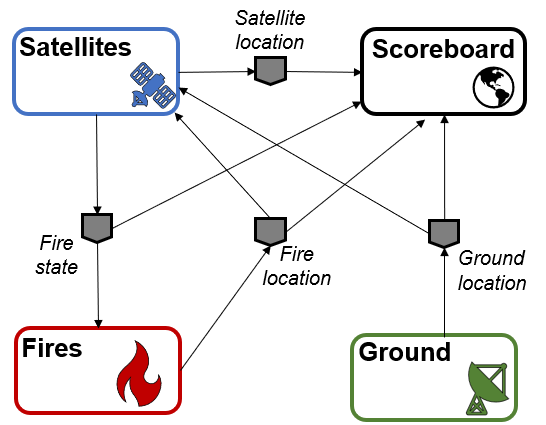
Figure 8. FireSat+ Test Case Event Publishers/Subscribers
Unmanaged Use Case
An unmanaged user application does not need to maintain an internal representation of time. It does not subscribe to manager control events. Instead, it triggers behavior in response to status events or events published by other user applications. For example, the Ground application in the FireSat+ case may not need an internal representation of time if it only triggers in response to a change in Mode Status issues as a message published by the Manager application. Similarly, the Scoreboard might subscribe to time status message events from the manager application to display the scenario clock, but it does not need to subscribe to any of the Manager’s control events in order to function. All the other visualizations on the scoreboard are triggered by status messages from the other user applications.
Unmanaged user applications do not need to use manager commands to run, instead they can be controlled solely through user commands. Although the Manager is not necessary to run unmanaged apps, testing has found that regular heartbeat messages are useful for users to know if their application is still running over long test cases. Figure 9 illustrates how user commands, not Manager application commands, start the user applications and they will continue executing until a user-issued STOP command, NOT a Manager-issued STOP command.

Figure 9. Behavior of Unmanaged User Applications. (click to enlarge)
Managed Use Case
A managed user application relies on the NOS-T manager application to control various aspects of the simulation. These include starting the simulation when all user apps are ready, governing and communicating scenario time, and finally terminating the simulation. Unlike the unmanaged use case, in a managed use case the Manager Application triggers behavior in the user application throughout the test case. This communication at its most basic level is seen in Figure 10. The Manager publishes messages to topics via the message broker. These topics are subscribed to by user applications. For example, the Fires/Science application in the FireSat+ test case may rely on periodic time status events (e.g., published every 6 hours of scenario time) to pull and update fire state information using the corresponding time stamp before publishing a new Fire Status event.
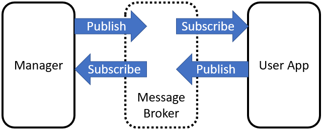
Figure 10. Basic Event Message Flow of Managed User Applications.
Figure 11 provides an overview of the types of messages that pass between the manager and managed user applications.
Figure 11. Simplified Behavior of Managed Application. (click to enlarge)
All messages between applications in NOS-T go through the message broker via a publish/subscribe method. To begin a test case execution, applications must subscribe to the Manager’s initialize command event to initialize, mode status event to enable/disable behavior, and time status event(s) to trigger temporal behaviors during a test case execution. The choice of Manager time status interval should be coordinated in advance to align with a managed application’s concept of operations. Figure 12 illustrates how the initialize event triggers an initialization activity, the EXECUTING mode status event triggers the start of a main execution loop, the time status event triggers response behavior, and the TERMINATING mode status event ends a test case execution.

Figure 12. Detailed Message Flow for a Generic Managed Application. (click to enlarge)
Table 10 contains the necessary events, seen in Figure 12, that are published for a managed application test case along with their publisher and a description of the message payload.
Message |
Publ isher |
Message Contents Description |
|---|---|---|
Initialize |
Manager |
Start and stop scenario times for a test case execution |
Ready |
User App |
Indicates this application is prepared to enter the simulation. |
Start |
Manager |
Gives wallclock and scenario start times, scenario stop times, and simulation time scaling factor. |
Mode: Initializing |
User App |
Tells manager app that the user app is in the process of connecting to the broker and establishing simulation variables |
Mode: Initialized |
User App |
Tells manager app that user app is ready to begin test case execution. |
Mode: Executing |
User App |
Tells manager app that the simulation is running with provided parameters. |
Time Status |
User App |
Publishes time status messages at a regular interval (scenario time). The interval is provided by the scenario start message and will begin at the time indicated by the scenario. |
Stop |
Manager |
Command to stop a test case execution by updating the execution end time. |
Mode: Terminating |
User App |
Tells manager app that the simulation is in the process of disconnecting from the broker. |
Mode: Terminated |
User App |
Tells manager that this user app has disconnected from the broker. |
Interface Requirements
The basic interfaces between the NOS-T system and user applications are illustrated in Figure 13. Since NOS-T is a defined system with established interfaces it will publish, subscribe, support, and provide the items shown. For the purposes of this ICD, these interfaces are a given and cannot be changed. To be compatible with the existing NOS-T interfaces shall subscribe, publish, support, and provide the items shown. These are shown as shall statements as they are mandatory interface requirements. Specific interface requirements with acceptance criteria are shown in Table 11.

Figure 13. Basic interface between NOS-T system and User Applications. (click to enlarge)
Number |
Name |
Description |
Rationale |
|---|---|---|---|
IR.1.0 |
Pub/Sub Messages |
User applications shall publish/subscribe to the following NOS-T Manager messages. |
User apps must be able to receive and send manager messages a test campaign to be orchestrated. |
IR.1.1 |
Sub Messages |
User applications shall subscribe to the following NOS-T Manager messages. |
User apps must be able to receive manager messages a test campaign to be orchestrated. |
IR.1.1.1 |
INITIALIZE Message |
User applications shall subscribe to the manager INITIALIZE message. |
The INITIALIZE message tells user application to prepare for the test case. |
IR.1.1.2 |
START Message |
User applications shall subscribe to the manager START message. |
The START message tells user application to prepare for the test case. |
IR.1.1.3 |
STOP Message |
User applications shall subscribe to the manager STOP message. |
The STOP message tells user application to prepare for the test case. |
IR.1.2 |
Pub Messages |
User applications shall publish the following messages to the NOS-T system. |
User apps must be able to receive manager messages a test campaign to be orchestrated. |
IR.1.2.1 |
INITIALIZED Message |
User applications shall publish an INITIALIZED message to indicate application are ready to execute. |
The INITIAILIZED message tells the manager that an application ready for execution. |
IR.1.2.3 |
EXECUTING Message |
User applications shall publish an EXECUTING message to indicate application have started to execute the test case. |
The EXECUTING message tells the manager that an application executing the test case. |
IR.1.2.4 |
TERMINATING Message |
User applications shall publish a TERMINATING message to indicate application is preparing to terminate the test case. |
The TERMINATING message tells the manager that it has received the STOP message and is preparing to terminate the test case. |
IR.1.2.5 |
TERMINATED Message |
User applications shall publish a TERMINATED message to indicate application has ended the test case execution. |
The TERMINATED message tells the manager that it has ended the test case execution. |
IR.2.0 |
Message protocols |
User application messages shall comply with standardized protocols. |
Standard protocols and encoding ensure interoperability with the NOS-T System and other user applications. |
IR.2.1 |
MQTT |
User application messages shall use MQTT communication protocol with the pattern: prefix/app/event (TBC) |
The event broker users the MQTT messaging protocol to publish and subscribe to event topics. |
IR.2.2 |
JSON |
User application messages shall use JSON formatting for payload information. |
The JSON encoding format is human-readable and easily serialized and de-serialized. |
IR.2.3 |
Encryption |
User application messages shall use TLS encryption technique. |
Encryption protects the contents of messages during transport from the client to the server. |
Test Case-Specific Execution Requirements
In addition to generic NOS-T interface requirements, each test case establishes specific requirements for its user applications. The test case-specific requirements include, but are not limited to:
Event topics, including which applications are publishers or subscribers.
Event message payload syntax and semantics.
Application behavior, e.g., response to specific events.
All user applications must subscribe to the manager application following their execution mode (managed or unmanaged) but can freely subscribe and publish to other user topics subject to access control rules set by the NOS-T operator. Publishing and subscribing to user applications should follow the topic hierarchy outlined in Section 3.2.1.
In general, user applications are recommended to use text message payloads encoded in JSON. Some existing standards such as the SensorThings API can provide guidance on object schema structure. SensorThings data event entities include a name field, description field, and properties sub-object in the JSON data. For example, the payload for a Fire Status event in the FireSat+ test case (published by the Fires/Science application and subscribed to by the Constellation/Satellites application) can be structured as:
{
  "name": "fire",
  "description": "Models the spread of a fire.",
  "properties": {
    "timestamp": "2019-03-13T04:11:40+00:00",
      "intensity": 35398693.13517181,
      "latitude": 42.49602475523592,
      "longitude": -103.69767511612058,
      "windSpeed": 5,
      "growRate": 1.705270367448615,
      "fireStart": "2019-03-13T00:00:00+00:00"
  }
}
Some test cases may require alternate communication protocols to overcome broker limitations. For example, some test cases may consider large data products that exceed the 30 MB maximum message payload. To exchange large data products, applications may establish an alternate hosting service (e.g., web server, repository, or network drive) and simply send an URI to the data in the message payload. Users also need to consider slowdowns due to overall message size, which are explored in the following reference[8].
Detailed User’s Guide
Defining Test Campaigns
For purposes of NOS-T system use, we have defined a test campaign to be an organized collection of test suites designed to collect data to accept or reject an observation strategy hypothesis (or hypotheses) as shown in Figure 14. Test suites are logical collections of test cases that differ from each one by ideally no more than one variable. A test suite considers different scenarios beyond the designer’s control (such as different fire ignition scenarios in the FireSat+ example), whereas the test cases each represent distinct design choices for the observation strategy in question. We envision that this collection of test suites and test cases comprises a test matrix developed using a rigorous application of Design of Experiments methods.

Figure 14. Hierarchical organization of test planning terminology used by NOS-T.
One approach to developing a test matrix for a user’s test campaign is to start by creating a variation of the traditional NASA Science Traceability Matrix (STM) that is focused on leveraging the NOS-T system to answer specific questions about observation strategies. A representative example for a NOS-T STM is shown in Table 12. This example includes two related but distinct objectives/test campaigns for the FireSat+ use-case. The STM is designed to help a principal investigator map out the metrics, user applications/nodes, their functional requirements, and test structure design. An example of a test campaign with results for Objective 1 in the table can be found in the appendix.
While use of this matrix is not mandatory from the NOS-T system perspective, it is suggested that any principal investigator should approach a test campaign with this level of rigor and that the questions and implementation approach highlighted by this matrix need to be defined well in advance of the campaign. A blank template for an STM is included in the appendix.
Table 12. NOS-T System Science Traceability Matrix (click to enlarge)
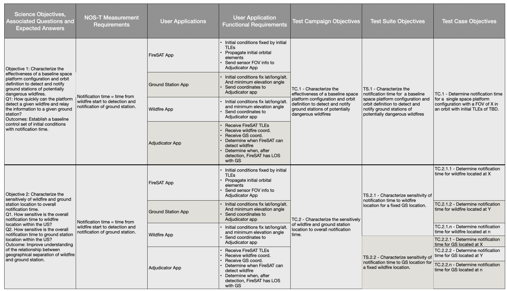
Each test campaign may comprise multiple test suites, each representing a different scenario beyond the designer’s control. In this example, the test suites are distinguished by the science application. Test suite TS.1.1 uses historic VIIRS fire data for the conterminous United States during the first five days of 2020, whereas TS.1.2 uses randomized global fire locations but with similar ignition schedules. Each test suite may comprise multiple test cases to evaluate different design choices for the observation strategy.
As any test campaign depends on the applications that will be employed, two other useful thinking tools to aid in user app coordination are suggested. The first is a Design Structure Matrix (DSM), which provides a method to represent dependencies among system modules as a square binary (0/1) matrix. The example in Table 13 shows the coupling between applications in the FireSat+ test campaign. It is read clockwise. So, in this example, data goes from the Satellite App to all the other three apps. However, the satellite app only receives inputs from the ground station and wildfire apps (not the scoreboard app).
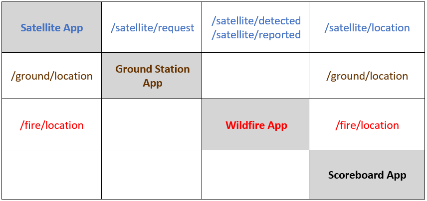
The DSM is useful for initial app-to-app interface planning. To examine the interfaces in more detail a second tool, a variation on the traditional NxN matrix, can be used. An example for the FireSat+ test campaign apps is shown in Table 14. The NxN is set up with the apps on the diagonal and interfaces, from and to, are again read clockwise. The items in the off-diagonal boxes represent messages being sent between user applications and are labeled with the message topics.
Table 13. NOS-T Design Structure Matrix for FireSat+ Test Campaign User Applications.
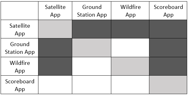
Table 14. NOS-T NxN Matrix for FireSat+ Test Campaign User Applications
Developing Applications
The NOS-T system serves as the airport, but the user applications are the airplanes that take principal investigators on their scientific journeys. The goal of NOS-T is to provide a universal interface and “flight control” infrastructure that can support any type of application that conforms to the basic interfaces described in this document. For that reason, it is outside the scope of this document to describe the internal functions of user applications. Users should apply their own internal systems engineering and software development processes and standards to ensure their applications meet their requirements (verification) as well as fulfill intended purpose (validation) of modeling real world observation strategy phenomena.
Tools, Templates, and Techniques
Table 15 and Table 16 below list tools and templates found in the NOS-T tools folder. The table gives a brief description of each as well as their object classes. The object classes are given in the order they are found in each .py file.
Tool |
Description |
Object Classes |
|---|---|---|
logger.py |
Records all messages published to a given topic in a .txt file |
N/A |
manager.py |
Defines a manager application (inherits Application class from application.py) to orchestrate test case executions |
TimeScaleUpdate Manager |
Property |
Description |
Object Classes |
|---|---|---|
application.py |
Contains functions to set up a user application and add/remove message callbacks. |
Application |
application_utils.py |
Contains helper classes for connecting an application to a message broker, shutting down the application on some event, and publishing time and/or mode status changes. |
ConnectionConfig ShutDownObserver TimeStatusPublisher ModeStatusObserver |
entity.py |
Contains the Entity class, which inherits properties of Observables (see observer.py) and maintains its own scenario clock. |
Entity |
managed_application.py |
Contains functions for a user application (inherits Application class from application.py) to handle external commands from a manager (see manager.py). |
ManagedApplication |
observer.py |
Defines classes for registering and notifying observers of property changes. |
Observer Observable |
publisher.py |
Defines classes (inherits Observer class from observer.py) for publishing status messages at regular scenario or wallclock time intervals. |
ScenarioTimeIntervalPublisher WallclockTimeIntervalPublisher |
schemas.py |
Contains Pydantic templates used for typical NOS-T Tasking Parameters and Commands. |
InitTaskingParameters InitCommand StartTaskingParameters StartCommand StopTaskingParameters StopCommand UpdateTaskingParameters UpdateCommand TimeStatusProperties TimeStatus ModeStatusProperties ModeStatus ReadyStatusProperties ReadyStatus |
simulator.py |
Defines Simulator class (inherits Observable class from oberserver.py) and its modes. Contains functions for adding and removing entities to Simulator. |
Mode Simulator |
Ensuring NOS-T Compatibility
Prior to participation in a test campaign, it is incumbent on users to ensure the compatibility of their applications with the NOS-T environment. At the most basic level, the only requirements for any application are the ability to send and receive messages to a message broker using the MQTT publish-subscribe network protocol and adhering to JSON standard format.
Additional compatibility checks are required if the application in question is intended to be a time-managed application, as this requires the application be able to receive and respond to commands from the manager. Most applications will likely need to be managed. The subscriptions to Manager commands and the published responses required include:
Initialize
Subscribe: Initialize command from the Manager on topic “{prefix}/manager/init” and update simulation start and end times accordingly
Publish: Send “ready” message to topic “{prefix}/status/{app}/ready when the application’s MODE changes from INITIALIZE to INITIALIZED
Start
Subscribe: Start command from the Manager on topic “{prefix}/manager/start”
Publish: Change application’s MODE from INITIALIZED to EXECUTING and begin to publish periodic heartbeat messages to topic “{prefix}/{app}/status/time”
Update
Subscribe: Update command from the Manager on topic “{prefix}/manager/update”
Publish: Set the time scale factor to the new value at the simulation time specified by the Manager and accordingly update the frequency of periodic heartbeat messages to topic “{prefix}/{app}/status/time”
Stop
Subscribe: Stop command from the Manager on topic “{prefix}/manager/stop}
Publish: Update the end time of the simulation (possibly overwriting original simulation end time) and change mode from EXECUTING to TERMINATING and then TERMINATED.
References
Appendices
Sample test campaign - Firesat+ - Objective 1
This test campaign corresponds to Objective 1 in the Science Traceability Matrix in Table 12.
For this test campaign, the metric of interest is the time between a fire’s ignition and when it is first detected by a satellite in the constellation or reported by that satellite to a ground station. Detection and downlink events are assumed to occur instantaneously once the satellite is within range. Consideration of data volumes, downlink rates, and time within range of ground station are reserved for future test campaigns. Summary statistics of center and spread for detect time and report time distributions were recorded for each test case. Initial tests of the integrated FireSat+ applications showed multi-modal detect time distributions because a single satellite will detect several fires in close proximity during the same time step given its instrument field of view. The report time distributions were even more biased towards multi-modality given that previously detected fires would all be reported simultaneously once the satellite comes into view of a ground station. For this reason, center and spread for these test cases are summarized by median and interquartile percentiles (25th and 75th) rather than normal distribution descriptive statistics (mean and variance).
Test case TC.1.1.1 represents a verification test conducted during application development using the historic TLE for the Suomi National Polar-Orbiting Partnership (NPP) platform that carries the VIIRS instrument, with the expectation that the fires would be “detected” immediately after ignition since the test used VIIRS detection times as historic ignition times. The subsequent test case used the same fire ignition schedule but with current TLEs queried from CelesTrak for fire-observing satellites Aqua (MODIS), Terra (MODIS), and Suomi NPP (VIIRS) considered as a constellation.
Test suite TS.1.2 is more representative of the comparative trade studies facilitated by NOS-T. Test case TC.1.2.1 uses the same TLEs as TC.1.1.2 to evaluate global coverage. Test case TC.1.2.2 considers an alternative architecture that replaces the Suomi NPP satellite with Sentinel-2A (MSI) and Sentinel-2B (MSI) which share the same orbit with a 180° phase difference. The VIIRS instrument has a much wider FOR (112.56°) compared to MSI (20.6°), so this test suite investigates tradeoffs between the number of spacecrafts in a constellation and instrument view angle constraints.
The four test cases defined in Table 12 were executed in two scenarios. The first scenario is limited to the first 100 fires from January 1, 1. The second scenario considers a longer duration from January 1 – 5, 2020 that increases the sample size to 298 fires. Summary statistics for detect and report times were recorded for both scenarios, with the results from the longer scenario displayed in Table 17. Most of the test cases in the short scenario had matching median and 25th percentile measures, suggesting this sample size is not large enough for a well-defined distribution. Results for the five-day scenario show more spread, as can be visually confirmed by TS.1.2 report time distributions plotted in Figure 15 and Figure 16.
Table 17. FireSat+ Summary Statistics: First 5 Days
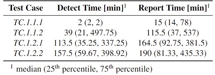

Figure 15. TC.1.2.1 Report time distribution coded by reporting satellite
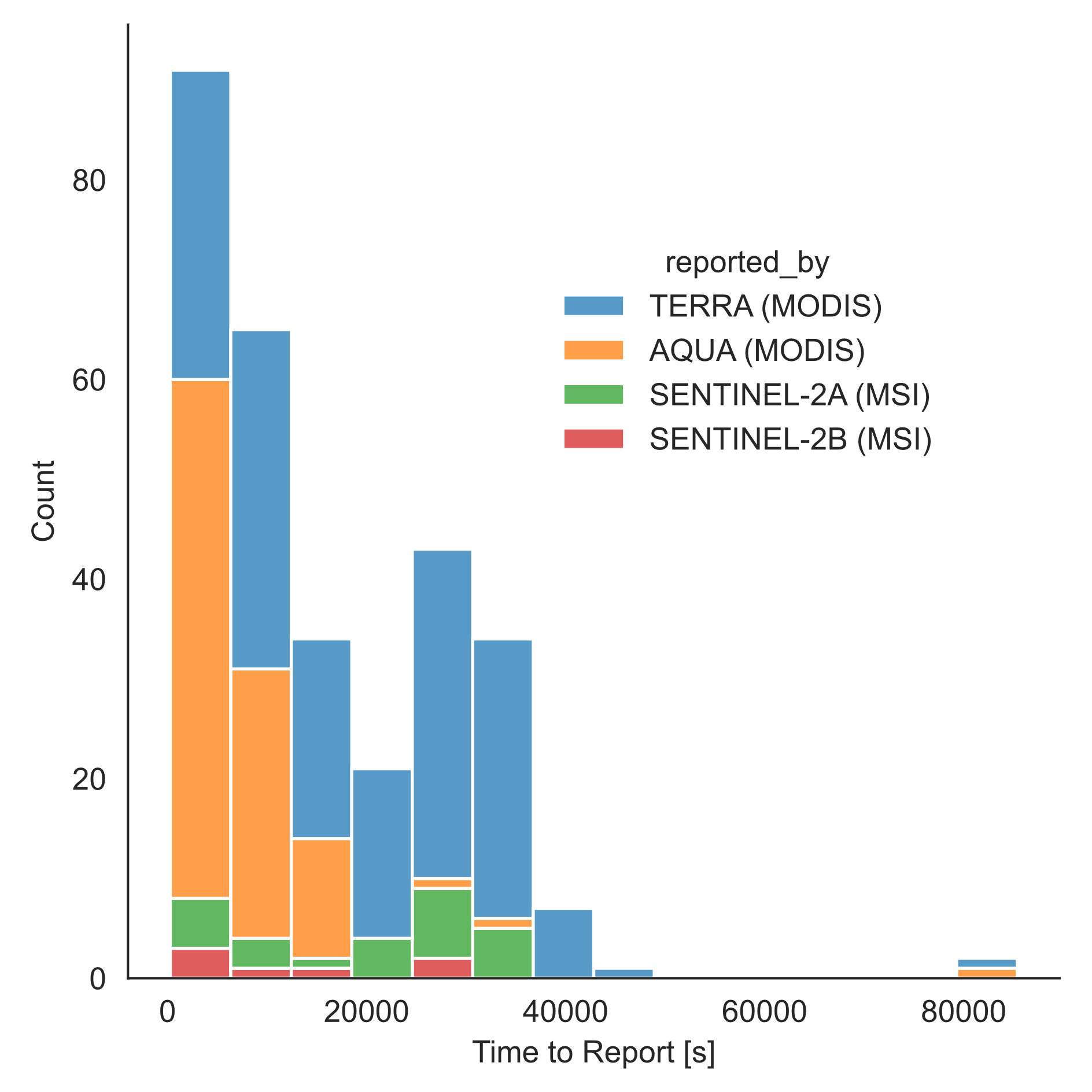
Figure 16. TC.1.2.2 Report time distribution coded by reporting satellite
Results are coded by reporting satellite for the stacked bar charts in Figure 15 and Figure 16 to show the relative contributions of each satellite in the constellation. These tests show that FOR constraints on the Sentinel spacecraft limit their contributions to the constellation performance relative to Suomi NPP.
Blank Science Traceability Matrix Template
Download a blank STM here